
What Is Fast Charge?
As a result of increasing the number of smart and electronic devices, it is more required to charge them as fast as possible; so this is the main challenge for engineers to power these devices up. One of the choices is to use batteries, which recently make progress in size and capacity by the help of technology. More capacity leads to less rate of discharge and smaller batteries are lighter. But still there is another challenge that is the time it takes to charge. In this article we’re going to teach you how to make a fast charger using CHY103 IC.
The more capacity a battery has, the more time takes it to charge. Imagine if you are in hurry to join a meeting outside of the city and unfortunately your phone has about 5 percent of electrical power. Using regular charger takes about 2 hours to reach fully charge and about 1.5 hours to reach approximately 70 percent and it could increase for phones with more battery capacitance. So you will miss the meeting.
What Is the Solution?
In 2013, Qualcomm company introduced Fast Charge technology for the first time which allows devices to maintain an acceptable charge level. Qualcomm company announced and developed 4 versions of Fast Charge.
It offers more power and thus charges batteries inside devices faster. The first version offers only 10 watts and the second one’s power supply increased up to 18 watts. The picture below shows all versions and explains some details.

The last Qualcomm’s technology, Fast Charge 4+, asserts that 5 minutes of charging gets you 5 hours of battery life.
How does Fast Charge works?
These are other companies which have developed Fast Charge technology but Qualcomm is known as forerunner. Furthermore, it uses common equipment, like used wires. We’re going to peruse Qualcomm recommended system.
The only solution for faster charging is to offer more power, which is possible by increasing current or voltage. The first version increases current up to 2 amps which caused in 10 watts. There’s plenty of problems and limitation about increasing current. The wire resistance is one of them that leads to more voltage-drop and more heat. Furthermore, some wires can’t carry more than 1 A current in reason of poor wire quality.
Duo to reasons above, the second version increased voltage instead of current. It increases power but wire has less effect on charging process. What’s more, there’s less heat and smaller charger is possible to make. The second version has more options to choose voltage between 5, 9 and 12 volts. The third version also has ability to determine voltage between 3.6 to 20 volts for used gadget.
How does Charger Choose the Proper Voltage?
As we discussed at the article named “everything about lithium-ion battery charger’s circuit” about charging Nickel Cadmium batteries, temperature is an important factor for charging batteries. As the battery charges, heat is generated that if it’s not controlled, either its value or increasing rate, battery can damage or even explode.
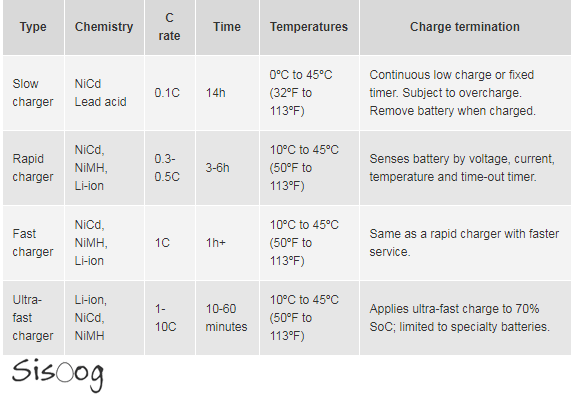
This table shows that increasing temperature depends on chemical structure and type of charging process.
Duo to increasing temperature peril, power must decrease to reduce dangers of battery damage.
Explanation about C parameter named in table:
If there’s a 2000 mAh and 3.7 V cell and discharging current is 2 A, it will discharge completely after 1 hour. But if 2 A current discharges the cell, first check the C-rate. charging capacity * amplitude(mAh) = maximum cell crossing current. Every cell has charging and discharging rate. If this battery C rate is 5, it could be charged by 10 A current. Most quadcopter batteries charging capacitance is 1 C and some of them is 0.1 C.
But how are chargers and smart gadgets connected and is the gadget able to control charger voltage?
USB chargers have 4 strings of wire which two of them named D+ and D- carry information. During charging process, when smart phone or any other gadget recognize the charger, the output voltage can be controlled by applying different.
these two wires’ voltages. First of all, charger shorts circuit these two strings of wire for the reason that phone understand charger is connected.
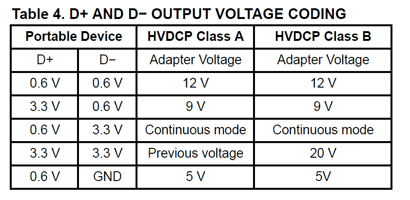
The picture above shows the Fast charger output which controls the output depends on D+ and D- voltage value. Notice that Fast Charger 3.0 has two classes whose difference is about maximum output voltage. Class B maximum output is 20 V.
How to Make and Implement Fast Charger
You need a circuit to control output voltage that depends on D+ and D- voltages another part to create voltage.
For the second part available regulator can be used. It is recommended to use switching and high-frequency types. We used LM2596 in this project.
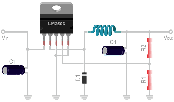
This regulator, LM596, operates at a switching frequency of 150 kHz with Guaranteed 3.0 A output load current and it is easy and convenient that needs little elements to set up. Adi type can control output voltage by resistance circuit.
The second part is the most important part of controlling. Instead of designing a circuit which control the output voltage duo to gadgets need or use some analog comparators, reference ICs and digital gates or using a microcontroller, as an easier way, it is possible to use designed ICs for this purpose.
Fast Charger Controller IC Introduction
we are going to use CHY103, produced by Power integrations company. This IC support both Fast Charge 3.0 classes and has a little power consumption about 1 mW.
It is designed to be directly communicated to Fly-back ICs, TinySwitch and TopSwitch. If we want to use other regulator ICs with this IC, it is needed to design feedback network without problems for connections.
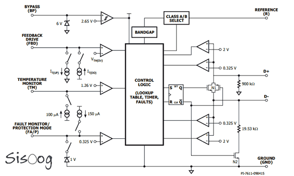
As you see in IC block diagram above, it uses 4 comparators and Control LOGIC decides about output voltage depends on these four.
This is the recommended circuit to use this IC.
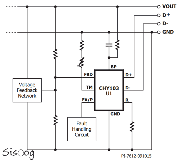
Pin2 (FA/P) can be used to shut down IC. When we want to delete CHY103 from feedback control circuit or regulator interrupts, we could use this pin.
We can select class A or B by choosing proper resistant at pin7 (PREFERENCE). We mentioned previously that class B of version 3 can has 20 V output voltage. Pin8 (BYEPASS) is used for identifying under-voltage and also provides needed voltage for IC function.
Pin1 (TEMPERATURE MONITOR) used for monitoring temperature produced by circuit and by less input power can prevent circuit damage. Just connect a proper NTC to it.
Pin2 (FEEDBACK DRIVE) is connected to main regulator feedback path to control and monitor output voltage. If you look at IC block diagram, it is cleared that this pin is connected to a comparator with Vth voltage and also can be leaded IT current. This mechanism helps to increase or decrease output voltage by changing regulator reference voltage.
Sisoog Fast Charger Circuit
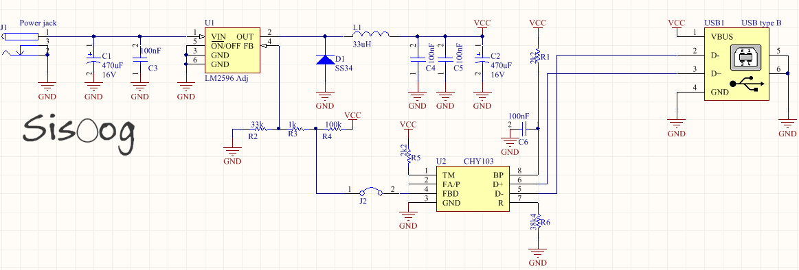
This is designed depends on LM2596 and CHY103 which fault handling part is ignored, temperature sensor is deleted and there is no need to assemble R5.
The most important part is designing feedback network values. The inner reference voltage of LM2596 is 1.23 V and this value for CHY103 is 1.265 V; this conflict makes all the primary calculation hard.
Besides, CHY103 current to control output voltage to feedback path is 2 Micro-Amps; feedback parameter must be designed properly that current be able to change output. We used R2, R3, R4. We recommend to use resistance with sum of 134 kΩ.
We used 33 kΩ and 1 kΩ to make up voltage difference between two ICs; base voltage is 1.256 V for CHY103 and 1.23 V for LM2596.
Sample Sisoog Fast Charge
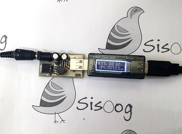
The picture above shows completed project, that is charging HTC M9.
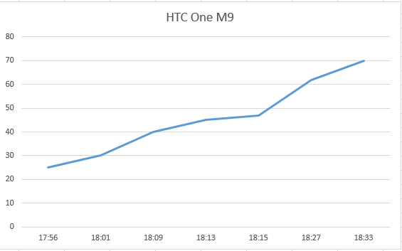
This charger is tested and compatible with LG, SAMSUNG and HTC mobile phones and charging process is without any problem.
Here is the HTC One M9 charging graph.
Download Fast Charge Schematic and PCB
Schematic and PCB designed by Altium Designer, that is free and open-source to use.
To download related files, go to sisoog GitHub account:
download QUICK-CHARGE-v3.0 project files
Author: Zeus
Translate: Golnoosh