
Unfortunately, there’s lots of open source-copied sources that has been sold on the internet; like learning-code remote control (Learning remote control). Obviously, open source resources had a great effect on advancement of technology, thus, it deserves not to sold them and share them free.
Today, remote controller usage is a lot, such as burglar alarm, automatic door opener and light controller, that all of them use the same principles that is wireless communication. There’s lots of application for sending information: the most common one is Infrared Waves and Radio waves, for example IW used in television remote controller. Here we discussed about radio-wave remotes, that need a carrier for sending the modulated information and then propagating it in free space.
There’s tow type of modulation: Analog & Digital. The carrier wave character, such as amplitude, frequency and phase, changed by the main information wave, depends on type of modulation.
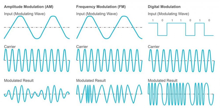
Type of Modulation:
As you see in the picture above, AM modulation changes the carrier amplitude; FM modulation changes the frequency of the carrier wave, that is better than AM because it has more effective area of aperture and decreasing the amplitude in AM means lower transmitter power. Digital modulation(Keying) look like frequency modulation.
Digital circuits use logic of 1 and 0 to represent information and for transfer information convert the to frequency F0 & F1. In this method receiver only has to detect difference between F0 and F1, and demodulate them to the binary number of 1 and 0. Radio remote controllers use this type of modulation or similar methods.
Learning-code remotes use ASK modulation for transferring data; it’s a simplified type of digital modulation in which F0 is deleted and just uses F1, it means, transmitter is turned on only when we have logic 1 and doesn’t generate any frequency as we have logic 0.
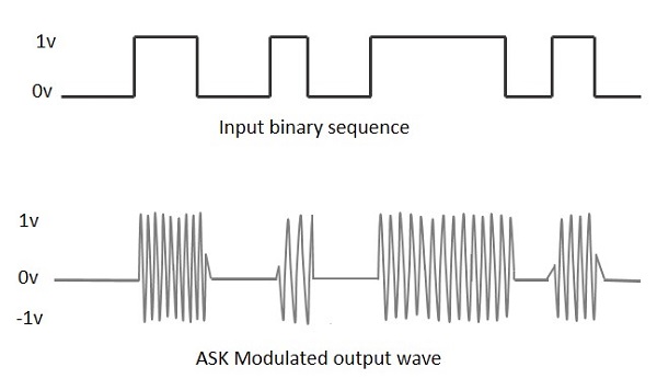
This method makes both transmitter and receiver more simple; because transmitter only generates F1 and receiver only detects F1.
Types of receiver’s remote
Till here, we’ve been learned about transferring information. Now we want to know about the remote controller; first, a remote controller needs to receive transmitter’s waves for user’s request after processing; referred to the type and frequency of transmitter we have to use the same frequency for remote controller, otherwise it can’t work properly.
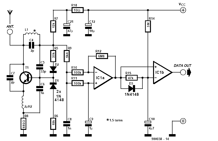
We can build our own receiver as you see it’s schematic below; but it is not recommended because of RF circuit complexity, instead you can ready modules and circuit.
Remotes normally use 315 and 433 MHz frequency, so pay attention to the frequency of both receiver and remote controller. We discussed two types of ASK receiver:
The elder one is a simple super regenerative transistorized circuit with low sensitivity, accuracy and price. This receiver needs 55 volts as operating voltage with 1 or 0 as outputs, but environmental noise can affect it a lot (picture below).
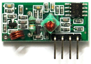
The newer one is a super heterodyne receiver with more complex circuit for demodulating data which uses quartz crystal, so it has good receiving quality and accuracy.
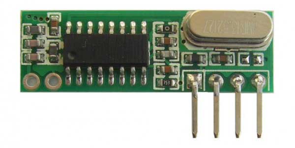
It can work with both 5 and 3.3 volt properly with data in output. The good news is that both modules’ pins is the same and could be replaced easily.
Learning-code protocol
After receiving data, we need to recognize transferring protocol for decoding. Before learning-code remotes, there was used fixed-code remotes with 8 pins; by connecting these pines to 1 or 0 in different ways they were coded, so, for matching receiver and transmitter, repeat this connection for receiver.
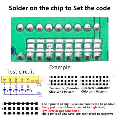
Now it’s obvious why it called fixed-code; so if we want to use another remote, it’s simple: just copy the transmitter’s code pattern;
but it is not a secure method because if anyone who find your code can make a compatible remote with your transmitter.
But learning-code remotes have more security. It means every remote has a 20 bits written random code in its memory. This code is unique for every remote, so for syncing, receiver has to save every remote’s code and for every request check if it’s a valid remote or not. Receiver learns the code!
Fortunately, both HS1527 and EV1527 (or similar families) use the same protocol and OTP encoder.

In this method we have 24 bits of data consist of 20 bits that is remote’s code and 4 bits for the remote’s buttons statues. First we have a Preamble situation then wait for 24 bits of data; so we need 3 unique situations:
- Preamble: in this situation if we have 1 for one µs, must have 0 for 30µ
- Logical 1: in this situation if we have 1 for 3 µs, must have 0 for one µ
- Logical 0: in this situation if we have 1 for one µs, must have 0 for 3 µ
Note that the times mentioned are for example and depends on inner oscillator; but ratios are true.
Remote program topology
I have been seen plenty of related codes both free or not; none of them uses principled method, some of them need a specific oscillator’s resistor (because only the value of zeros was checked), some didn’t use a good board, or remote didn’t work properly because of low battery level and made lots of problem.
After that you became familiar with remote function, now it’s time to write a program that recognizes receiving data and reacts to it depends on available features and options. The best solution for decoding data: at a clock’s positive edge, a counter start to count and at clock’s negative edge read counter’s value and set it zero, at the next positive edge compare previous and current counter’s value, that should be one of the above situations; pay attention that you follow the remote pattern of receiving data (first Preamble then 24 bits of valid data) because, otherwise, noise can affect the remote at random.
The important question is about counting rate(frequency) for accuracy of measuring pulse width; to answer this question take a look at datasheet of IC; we face this table:
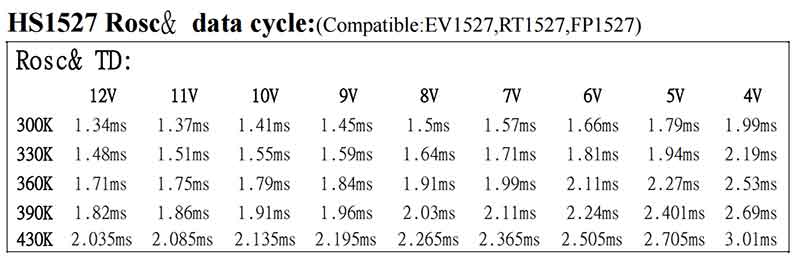
This is necessary time for transferring one frame (24 bits plus Preamble) of data depends on voltages and oscillator’s resistor. The shortest time is 1.34 milliseconds for transferring a frame. Every frame contains 126 pulses, so, every pulse will be 10 microseconds; if counter counts with 1 MHz frequency (1 microsecond), we are able to measure a pulse width with a good accuracy.
Explain the existing source
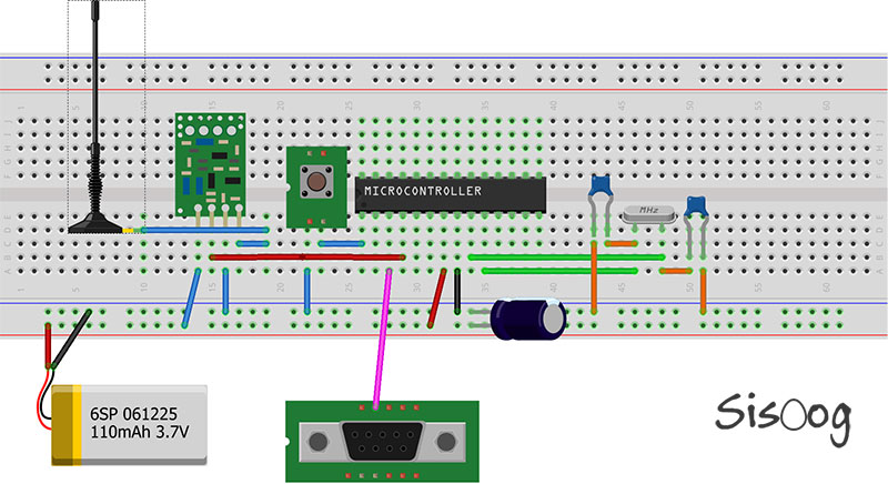
There’s two versions of source code (for ATMega8 microcontroller): Code Vision and GCC. Receiver’s data output connected to IC’s pin number 4 that interrupt’s input pin is zero (for detecting edges) and for measuring every pulse width using timer 0. This program is portable that you can use any microcontroller and using external oscillator with 8 MHz frequency.
This code was tested with 3 type of remote controller; both 315 and 433 frequencies. Testing with remote-433 worked about 8 meters without receiving antenna!
Download Source
[download id=”23812″]
[download id=”23815″]
Author: Zeus
Translate: Golnoosh