In the seventh part of STM32 tutorial with LL functions, we talked about the interrupt and the reasons why interrupts are useful. In the following we talked about interrupt in STM32 microcontroller in F1 series and how NVIC works. Finally, we did an external interrupt on a microcontroller pin.
In this part of the tutorial, we want to talk about the UART protocol in the STM32 microcontrollers.
First, we explain the theory regarding the UART with details and then implement this protocol in a microcontroller.
UART(Universal asynchronous receiver-transmitter)
Before talking about this protocol, let me remind you of this point that UART is derived from USART which the letter S in the USART means Synchronous. Due to less usage of the synchronous part of this protocol , is better known as UART.
Now, you may ask yourself what the meaning of Synchronous and Asynchronous is. In the digital electronic circuits when we use the name Synchronous, definitely in our circuit we have a signal which name is CLOCK signal.
As reminder digital electronic circuits are divided into two general categories, Combinational and Sequential. In addition, Sequential circuits are divided into two categories: synchronous and asynchronous. In synchronous sequential a circuit always works by a factor which name is CLOCK.
But there is no CLOCK signal in the asynchronous circuits and is coordinated based on another parameter that I will explain below.
So far, we understand that UART is categorized in synchronous circuits and USART categorized in asynchronous circuits.
UART is serial communication protocol consists of a sender and a receiver that can transmit and receive data from a node to another node any time. This feature is called Full duplex.
RX and TX pins in UART protocol
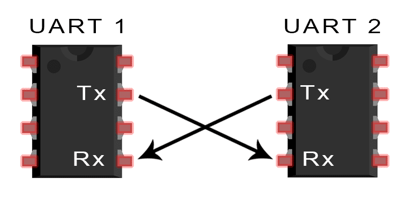
The above image demonstrates two chipsets that support the UART protocol. It is clear that in the UART protocol plus GND which is common in all protocols and is a criterion for measuring the other signals, there is two other main pins namely RX and TX. RX means Receiver and TX means Transmitter.
If you look at this image carefully, you will see that the TX pin from the first device is connected to the RX pin of second device and the TX pin of the second device is connected to the RX pin of first device. The reason of this connection is that when the first device send data on TX pin, on the other side the second device receives the data on RX pin.
How to transfer data in the UART protocol
One of the main factors in knowing a protocol is to be familiar with the data transmission on that protocol.
In every protocol there are a series of rules which are provided by manufactures which these rules explain the data transmission way.
In the UART protocol, a series of rules have been established for data transfer that we survey them in the following.
First, look at the below image:
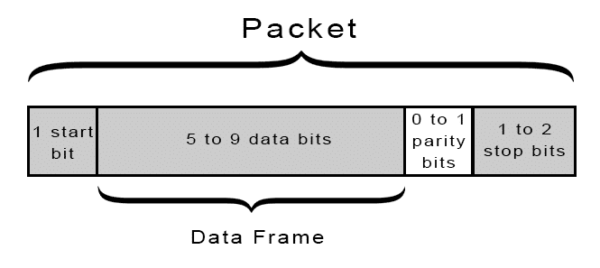
In the above image an image of data packet was displayed, and this packet has the following details:
Start bit: this bit of the packet which its value is zero, indicates the start of sending packets and give notice to the receiver that packet sending is started.
Data Frame: after the start bit is transmitted it is turned to send out desire data to receiver. The data can consist of 5 or 9 bits, but mostly 8- or 9-bits data is uses.
Parity bit: parity bit is a criterion for measuring the error. This bit is optional, it means that the packet can have this bit or not. the value of parity bit is calculated in both side and compared together. if this value is not same on both side it means there is an error in data receiving and the captured data is wrong.
For more information search about the parity bit.
Stop bit: this bit of the packet has the logical 1 value and notices to the receiver that the transmission is finish. As it is obvious in the above image stop bit can also be increased from 1 to 2 bits.
Well, we talked about a packet of UART protocol and said what is the usage of each part of the package. But there is another important factor in this protocol that name is Baud Rate.
Baud rates actually determines how many bits of data are transferred in one second. If you remember at the beginning of the article we said that a factor causes the work and coordination of synchronous circuits is CLOCK but in the asynchronous circuits there is no CLCOK, and baud rate does this for the circuit.
In the data frame it is too important to know the exact time of transmission. Actually, the baud rate defines this time for us.
Ther are a variety of baud rate in this protocol but usually baud rates 9600 and 115200 are mostly used.
UART protocol in STM32 microcontrollers
In the STM32 microcontrollers, plus all the above-mentioned cases regarding the UART protocol, many other peripherals are supported for UART. In the ST documents these peripherals are considered as important features.
But each of these peripherals should be explained separately and we describe them in next articles. So, in this case we just focus on UART protocol in the data transmission mode.
Let us start STM32CubeMX software and setting up the UART in transmission mode.
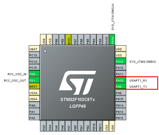
First, we set the Clock and Debug like the past and then from the connectivity which is related to supported protocols from the microcontroller, enable the USART1.
After enabling the USART1 we will see that two pins correspond to USART1 have changed like below image:
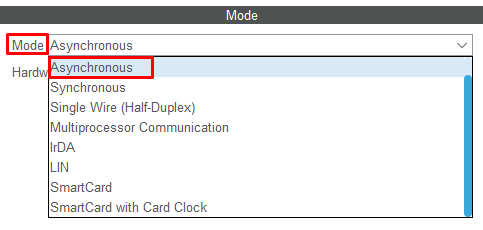
Now, we should define that we want to use synchronous or asynchronous mode of USART1. If we choose synchronous mode is corresponded to USART and if we choose asynchronous is equal to UART.
But as I mentioned above we would like to use asynchronous mode which is UART.so we choose asynchronous like below.
Due to the UART frame packet, Baud rate, Word length, Parity and Stop bit were variable parameters and we should define them based on our demand.
First, pay attention to the below image:
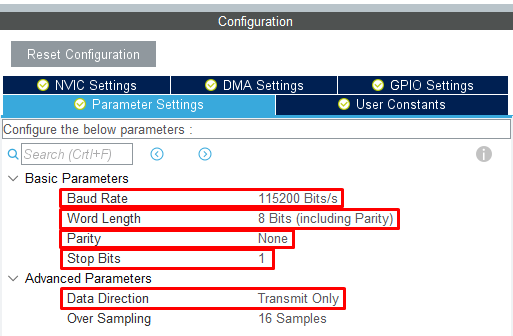
As you can see we set the Baud rate to 115200 per second. This microcontroller supports Baud rate ranging from 245 bit per second to 1000 kilobit per second.
Data length in this microcontroller is supported two values of 8 and 9 bits. According to the explanations we gave parity bit can be absent in the sent packet or it can be present and has one of the modes either even or odd. We setup the parity bit on None mode which is means we do not want parity bit to be in our transmission packet.
Finally, for Stop you have two choices between 1 or 2, we set it on 1.
Also, we want to just send only data so set the Data direction on Transmit only.
After the above setting we execute the project and get output then enter to Keil code editor.
At first, we define a const array called Name. the type of this array is Char and the length of it is 6. We put the string with this value “Kamin” in this array.
Also, we define an 8-bit variable called i with type uint8_t for the counter.
Our method is that we want to send the array called Name and has string “kamin” through microcontroller UART to computer and see the result.
First, look at the code inside while loop:
|
1 2 3 4 5 6 7 8 |
LL_USART_TransmitData8(USART1, Name[i++]); while(!LL_USART_IsActiveFlag_TXE(USART1)); if(i == 6) { i = 0; } |
At first we send the first character of the Name by UART1 through the LL_USART_TransmitData8 to the computer. In order to be able to send the second character and so on until the last character to the computer, we should survey that the transmit register is empty or not.
Let us before explanation of how to survey the transmit register whether the transmit register is empty or not, talk about the background of data transmitting using UART in the microcontroller.
When we tent to send data by using the LL_USART_TransmitData8 through UART, our data is placed in the Transmit Data Register (TDR). After placing the data in this register, a shift-register that is called Transmit Shift Register is responsible for placing the data in Transmit Data register on the TX pin of the microcontroller.
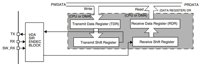
After placing the data from Transmit Data Register (TDR) in the shift-register completely and data transmission starts, the eighth bit of the Status register called TXE becomes 1 and is shown that we can put the next data in the Transmit Data Register (TDR) without any fault.
Pay attention that TXE bit from the Status register is just read only and its value changes by hardware and we cannot be able to change this value through the software or program, just we can read its value.
So, in short, when we write data in Transmit Data Register (TDR), TXE bit changes to 0 and when this data is placed in the shift register completely and the data transmission is started changes to 1. All of these changes are hardware.
According to above mentioned by using the LL_USART_IsActiveFlag_TXT, we surveyed in the program when the value of TXE bit is 1 and until this bit becomes 1 the program waits for data to be sent and when this bit becomes 1 the next data be placed in the Transmit Data Register (TDR).
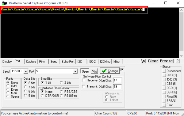
We also checked using the conditional if structure that if the last character of the string is sent, returns to the beginning of the string. Actually, we sequentially send the string “Kamin” to the computer using UART.
After executing the program, we connected the USB to TTL converter between microcontroller and computer. You will see the string “Kamin” sequentially sent to the computer serial port.
In this part of the tutorial, we surveyed the UART protocol and sending data. In the ninth part we will talk about receiving data by using the UART protocol.