In the eighth part of STM32 tutorial with LL functions, first we talked about the basics of UART protocol and describe that a data packet in this protocol includes what parts and at what baud-rate this data can be transmitted.
Finally, we surveyed the UART protocol in the STM microcontrollers and implemented the data transmit on the board.
In this part we want to setup the UART-Receive part.
The challenge of receiving data in the UART protocol
If you remember from the previous part, when we have aim to send data we put it in the transmit buffer (Transmit Data Register(TDR)) and after putting the whole data in the buffer the transmitting was started. By using the TXE bit we are informed that we can put the next data in the transmitting buffer. For reading the data by UART the principles are different a bit.
This difference is derived from the fact that we know when we are going to send the data, but we do not know when the data are going to be send toward us. This unknown time makes a problem in receiving a data.
The solutions for UART data receiving
To solve this problem there are two methods. One method is that waiting for data and when the corresponded buffer is filled then we catch the data. This method is not rational due to the high demand of microcontroller process and if we use this method we may lost some data when we are processing received data.
The minimum processing power that causes no data to be lost is the power that can overcome the speed of replacing new data with previous data in the buffer.
The second method is based on the interruption, so we recommend that review the seventh part of the tutorial regarding the interrupt.
Actually, the second method is related to the interrupt application. When the receive buffer is received data through the RX pin, the interrupt flag in enabled and we know that receiving buffer should be surveyed.
So, each time from the UART interrupt flag we were informed that data is stored in the received buffer, we should save the data in interrupt function.
To understand what happens in the lower layer when an interrupt occurs, first pay attention to the below image:
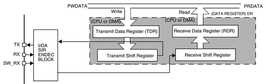
When the inside data on PDR shift register is transferred into USART_DR register, the sixth bit of Status register which is called RXNE, its value becomes 1. This means that we can read the inside data of the USART_DR. Whenever the data inside the USART_DR is read, the RXNE bit becomes 0.
After setting RXNE bit to 1 and reading the data from USART_DR register actually we have used inappropriate way like the first method. If we do this all the microcontroller power is dedicated to read the data.
But our solution is using the interrupt. To use interrupt after becoming RXNE bit to 1, another step must be taken so that we can use the UART interrupt to receive data.
When RXNE bit becomes 1,if the RXNEIE which is related to UART interrupt is also active, then a UART interrupt will be generated.
UART interrupt
Pay attention to the below image that demonstrates the generation of UART interrupt :
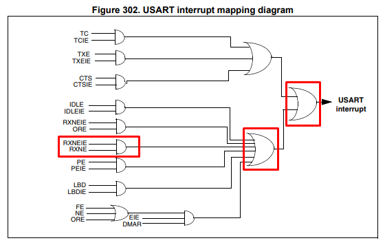
Next, according to the image above we tell you about an important issue regarding the code inside interrupt service routine function.
Before mentioning this issue consider that all the UART peripheral has just one interrupt and various factors causes this interruption. In the following of this article because of one interrupt service routine for UART peripheral we call the factors that cause this interruption an event.
As the above image demonstrates, there are several different events related to UART like sending and receiving data. All the events in this image have same trend, so we just survey one of these events which is related to receiving the data.
If we would like to have an interruption when the value of RXNE register becomes 1, we should enable the RXNEIE bit which means that write a logical 1 in this bit.
Now, if the RXNE bit is enable or its value is 1, each time the RXNE bit value changes from 0 to 1 and shows that data is ready to read the UART interruption is generated.
But this interruption is not only for receiving data, but all the UART events namely sending and receiving data generate this interrupt in the end.
So, if there is just one event, how we can distinguish between data receive of sending or other events.
Let us survey the details at first and explain how several UART events creates just one interruption, and after these explanations, give the solution of how to find out which event is occurred.
In the above image two RXNE and RXNEIE bits through an AND gate is ANDed together. The result of this operation on these bits and other bits are OR together and finally after passing through an OR gate are ended to USART interrupt as well as create UART interrupt.
So, the reason that we have just one interrupt been that all these events finally are ORed together.
The way to check which event the interrupt is related, is checking the corresponded event bits. As an example, for receiving data, we should survey in the interrupt function two RXNEIE and RXNE bits. You will understand this better when we write the function and code.
We explained everything you need to know about UART hardware details, events, and interrupts in the above. Now let us to set up the STM32CubeMX and UART in receive mode.
UART-Receive configuration in STM32CubeMX software
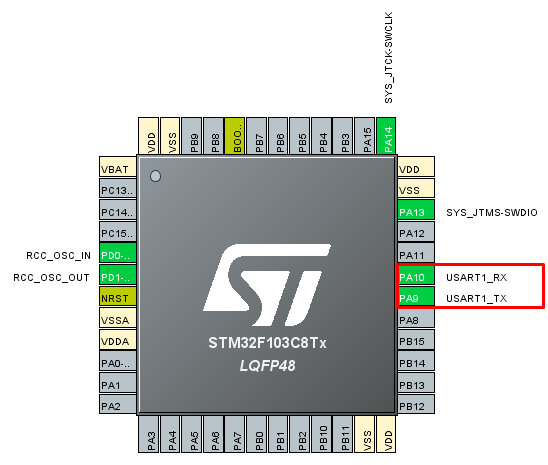
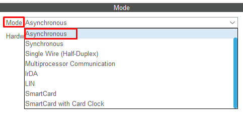
First, we set the clock and debug as before and then from Connectivity part we should enable the USART1.
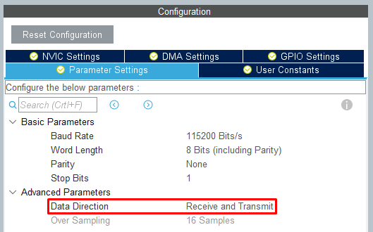
We set all the sections except for Data Direction, which must be in Receive and Transmit mode, as in the eighth part of tutorial.
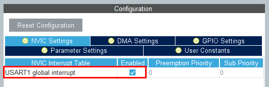
We also enable USART1 global interrupt from the NVIC Setting section to enable the UART interrupt.
After making the above settings we get the output of the project and then enter the Keil code editor environment.
The program that we would like to write in the following receive some character through interrupt and we put these characters together to make a string then, we break down the string into its constituent characters and send them on UART in UART-Transmit mode. We will see this string in PC serial port.
In the program first we have defined an array called Value_RX with char type and length 5 to save the received characters in this array. Also, we define three 8-bit variables with uint8_t type called i and j for counter and x for detecting receive or transmit mode.
It is enough to trigger the receive event just by writing the below code in main before while loop:
|
1 |
LL_USART_EnableIT_RXNE(USART1); |
First, look at the below code which is interrupt function:
|
1 2 3 4 5 6 7 8 9 10 11 12 13 14 15 16 17 18 19 20 |
void USART1_IRQHandler(void) { /* USER CODE BEGIN USART1_IRQn 0 */ if(LL_USART_IsActiveFlag_RXNE(USART1) && LL_USART_IsEnabledIT_RXNE(USART1)) { Value_RX[i++] = LL_USART_ReceiveData8(USART1); if (i > 4) { i = 0; x = 1; } } /* USER CODE END USART1_IRQn 0 */ /* USER CODE BEGIN USART1_IRQn 1 */ /* USER CODE END USART1_IRQn 1 */ } |
Well, as we mentioned before all the UART events have just one interrupt event with the occurrence of each event, only this USART1 global interrupt or USART1_IRQHandker function will be activated. To detect which event has occurred we should survey the corresponded bits inside the USART1_IRQHandler function.
We surveyed the RXNE and RXNEIE bits through if condition inside USART1_IRQHandler in the above code. if the value of these bits were 1 then the received characters from the UART port are placed in the Value_RX array. Whenever the Value_RX is filled completely we change the value of i which is the counter to 0. Value of x which shows the receive or transmission mode should change to 1 to enter the sending mode.
After completing the code inside the USART1_IRQHandler function in the stm32f1xx_it.c, return to the main program and write the following code inside the while loop:
|
1 2 3 4 5 6 7 8 9 10 11 12 |
if (j < 5 && x == 1) { LL_USART_TransmitData8(USART1, (uint8_t)Value_RX[j++]); while(!LL_USART_IsActiveFlag_TXE(USART1)); } if (j == 5) { j = 0; x = 0; } |
We change the value of x to 1 after receiving the whole characters. This causes we change the program into sending mode so in the above code the if condition is true and the received string will be parsed into its constituent characters and sent on the UART port. After sending the string completely we set the value of variable j which is a counter to 0 and the value of variable x to 0 to enter the receive mode again.
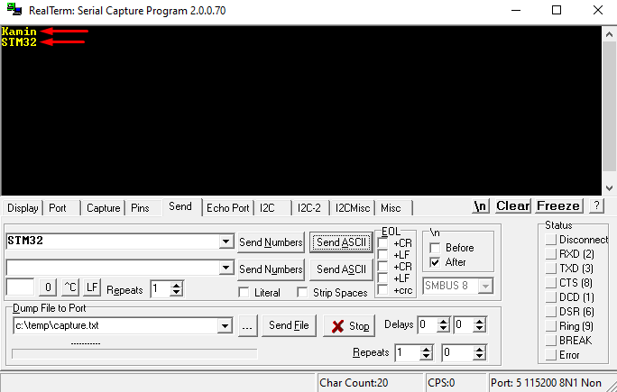
The function of the program is that it receives a string from you and then sends the same string to you on the UART port and waits for new string. Pay attention for the simplicity of the program, we consider the string length 5 characters. If you want to test this code consider same character for the UART buffer and send 5 characters.
To test the code, we used RealTerm software. After sending “Kamin” and “STM32” you will see the below result.
In the tenth part we will talk about the analogue to digital converter (ADC).