In the sixth part of tutorial with LL functions, we talked about the GPIO Input mode and showed the corresponding numbers of a counter by a push-button on a 7-segment.
In this part of the tutorial, we would like to talk about the Interrupt.
First, we will talk about what is interrupt and the explain how interrupts work in the microcontrollers and how they are implemented in a microcontroller.
Interrupt
As it is clear from the word Interrupt, it causes an interrupt in the process or doing something. In the digital electronic and the microcontroller in the meaning is same.
When a CPU during its normal work faces an Interrupt for a while pause the normal routine and executes the subroutine program. (Of course, the above explanations are generally stated, we will talk about the details precisely in the following).
Interrupt in the STM32 F1 series
We have a variety of interrupt in the STM32 microcontrollers such as External interrupt, Timer interrupt, Analog to Digital converter, Communication interrupts like UART and other interrupts which related to microcontroller hardware manger.
Interrupts of this category of microcontrollers have a series of special features that in the following we survey them.
NVIC (Nested Vectored interrupt controller)
NVIC means nested interrupt vector controller. Unlike AVR microcontroller in ARM microcontroller interrupts have priority. To elaborate on this let us talk about nested interrupt.
In AVR microcontrollers if an interruption occurs, the server function corresponding to this interrupt is executed.Now, if a second interruption occurs during the execution of this function nothing will happen. In fact, the second interrupt will be handled when the code inside the service function of the first interrupt has been fully executed.
The method of performing for both AVR and ARM is same but has a vital difference. Assume the first interruption has occurred and the microcontroller handles this interruption, meanwhile a second interruption occurs. Now, microcontroller decides based on some conditions either handles the second interruption or continue to handle rest of the first interruption.
What are these conditions?
In ARM microcontrollers each interruption has a priority level and NVIC regarding the priorities handles these interruptions. So, when the first interruption is in progress if another interruption occurs, the second interrupt is handled only if it has a higher priority, otherwise NVIC ignores seconds interruption until the operation related to the first interrupt is completed.
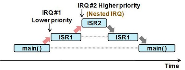
Now, we assume the progress corresponding to the first interrupt is running and an interruption with higher priority occurs, what will happen?
The operation corresponding to the first interruption is paused for a time and NVIC handles the interruption corresponding to the second interruption. After finishing the progress of second interruption, the operation related to the first interruption will be handled.
To understand the above mentioned completely pay attention to the below image.
In microcontrollers F1 series we can have 16 priorities for interruption. Setting these priorities is done using 4 bits, which include a total of 16 different modes.
As we mentioned there are many interruptions and it is not possible to explain them in an article, so in this part we just pay attention to External interrupt and talk about other interruption in the corresponding part.
External Interrupt
Totally, in the F1 series of STM32 microcontrollers we have 16 external interrupts on GPIO pins.
First, pay attention to the below image which shows the location of these interrupts:
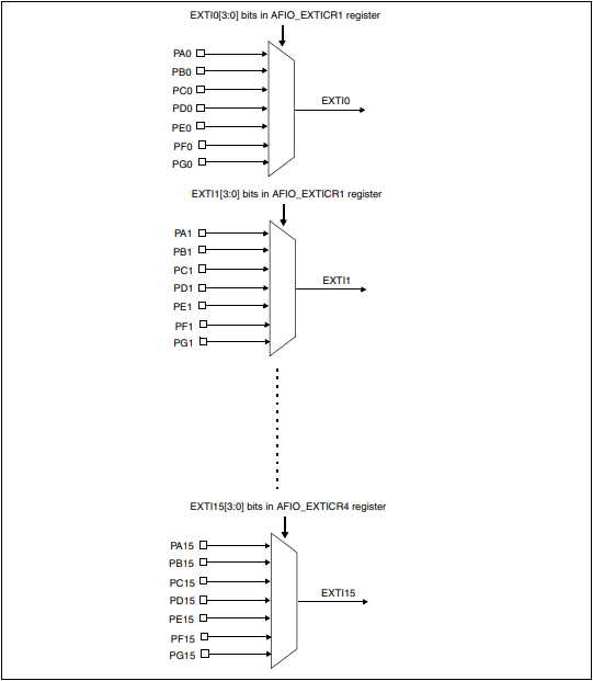
As can be seen from the above image, each line of external interruption is connected to the multiple GPIO through a multiplexer.
It can be deduced from the above image if an interruption occurs on the line number 1 which is corresponding to the EXTI1, this interruption is corresponded to one of the pins PA1 to PG1. Exactly which of these pins caused the interrupt should be defined in advance. We define in a register which output of the multiplexer is corresponding to the inputs.
Note that we cannot utilize two pins with the same number of two different port simultaneously as external interrupt, the reason is in the above image. If you do not understand the reason for this, please look at the image again and read the description again.
ISR (Interrupt Service routine)
When an interrupt occurs, the time to handle it reaches. The question is that how to handle the interruption and where we can notice an interruption occurs?
For a detailed explanation of what exactly happens when an interrupt occurs, we need to get into the details of the Cortex-M3 processor. we do not want to describe all the details because it may cause confusion for the readers of this article a just to elaborate, we cite important details in the following, very briefly and simply.
It is very simple to know that an interruption has occurred. By checking the bit corresponding to each interruption in Pending register we can notice an interruption is occurred or not.
But the main issue is that how we should handle the interruption once we know it has occurred. This duty is with ISR. ISR is abbreviation of Interrupt Service routine and is activated by hardware and does the codes that we need to be executed when an interruption occurs. Just we should put the codes in corresponding function when ISR runs.
So, we conclude that when an automatic interrupt occurs, the corresponding ISR is activated by hardware, and we should put our codes in the specified area in the function to be executed.
We explain in the Keil software regarding where these codes should be written in the program and inside what function.
As we mentioned, we have 16 external interrupts on the GPIO pins totally. Do each of these external interrupts have their own ISR? No, multiple external interruptions may together have only one ISR.
In the F1 series of STM32 microcontrollers which Cortex-M3 is their processor, external interrupts number 0 to 4 separately has ISR as well as external interrupts number 5 to 9 all together have one ISR and interrupts number 10 to 15 have all together one ISR.
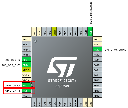
Now it is the time to implement all these things practically. We aim to enable external interrupt on the PA1 pin and connect this pin to a push-button. Now if this push-button is pressed 5 times, one LED which is connected to pin PA0 turns on and if again this push-button is pressed this LED turn off.
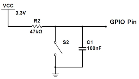
We should connect the below circuit to pin PA1 to prevent the push-button debounce and each time the push-button is pressed, there should be only one interruption.
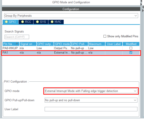
We set the CLOCK and DEBUG setting like the previous part. We set pin PA0 on GPIO_Output and pin PA1 on GPIO_EXTI1.
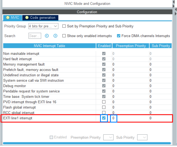
We set the interruption on the 0 priority with the falling edge which means when the voltage level of the GPIO of the microcontroller changes from the high to low it means an interruption occurs.
After completing the above steps, we get the output of the project and enter to the programming environment.
First, we define a variable and this variable increases by each interruption. How to increase the variable by one unit when an interrupt occurs? As we mentioned previously when an interruption occurs, corresponded ISR to this interruption is activated. After ISR activation, a function is recalled and each code inside the function is executed. Now, we should find the function and put our code inside the function.
The functions related to interrupts are in stm32f1xx_it.c file, we should explore for a function corresponding to pin PA1. The name of this function is EXTI1_IRQHandler. We should increase the variable inside the function according to the following code.
|
1 2 3 4 5 6 7 8 9 10 11 12 13 14 15 16 17 |
void EXTI1_IRQHandler(void) { /* USER CODE BEGIN EXTI1_IRQn 0 */ /* USER CODE END EXTI1_IRQn 0 */ if (LL_EXTI_IsActiveFlag_0_31(LL_EXTI_LINE_1) != RESET) { LL_EXTI_ClearFlag_0_31(LL_EXTI_LINE_1); /* USER CODE BEGIN LL_EXTI_LINE_1 */ i++; /* USER CODE END LL_EXTI_LINE_1 */ } /* USER CODE BEGIN EXTI1_IRQn 1 */ /* USER CODE END EXTI1_IRQn 1 */ } |
Inside the above function and code, we checked a condition whether an interrupt occurred on pin PA1 or not. If an interruption occurs, first clear the interrupt flag bit, and then add one unit to variable i. from now on when an interrupt occurs on pin PA1 the ISR automatically enable and the EXTI1_IRQHandler is called, and the variable increased one unit.
You may ask the reason of clearing the flag bit corresponded to the interrupt!
Well, as we mentioned before some interrupts have only one ISR and function and we should survey inside the function which of the interruption occurred and which function corresponding to the same interruption are executed.
We clear the flag bit of interruption due to every time the function is called, the modes inside the interrupt condition that did not occur will not be executed.
Maybe you got confused about this subject so to elaborate on this pay attention to this example.
As you know external interrupts number 5 to 9 altogether have one ISR and function. So, when each of the interrupts from 5 to 9 occurs, just one function is called. Now consider that we want if interrupt number 5 happens variable A increases one unit and if interrupt number 6 happens variable B increases one unit. If inside the function we increase the variables A and B without any condition, with each interruption both variables increasing and we do not have any control on interrupts, so using of the conditions are mandatory.
Now, consider that we use a condition for each interruption without clearing the flag bit. What will happen?
Assume that interrupt number 5 occurs, and the function is called and inside the condition the variable A increases one unit. We do not clear the flag bit.
Next time when interrupt number 6 occurs and the function is called, what will happen? Because we did not clear the flag bit corresponded to interrupt number 5, the condition of interrupt number 5 still remains, even though the interrupt number 6 has occurred the variable A increases again, and we do not want this issue. So, it is mandatory to clear flag bit in each condition.
Now, we put inside the Main and While loop this code:
|
1 2 3 4 5 6 7 8 9 10 11 12 13 |
if (i > 5 && State == 0) { LL_GPIO_SetOutputPin(GPIOA, LL_GPIO_PIN_0); i = 0; State = 1; } if (i > 5 && State == 1) { LL_GPIO_ResetOutputPin(GPIOA, LL_GPIO_PIN_0); i = 0; State = 0; } |
Well, as we said inside the stm32f1xx_it.c file and EXTI1_IRQHandler function we defined by each interruption, variable i is increased one unit. In the main of the program, we do the configuration on the variable i to turn on and off the LED.
So far, we have explained comprehensively all about the External interrupt. Other interrupts will be described in the corresponded articles of this tutorial.
In the eighth part we will talk about the UART-Transmit.