
In the fourth part of LL functions tutorial, we talked about RCC and the configuration of the Clock source for a microcontroller. Also, we described the reason of the Clock pulse in the digital circuits.
In the following we introduced the Reset circuit and told that when the reset occurred what occurs in the microcontroller practically. At the end we suggested a simple tutorial board that helps you to implement the codes on it.
After four episodes of tutorial, we can say that we passed the preparations and is supposed to start the microcontroller programming in the higher level. So, follow the Sisoog for the first step.
What are we going to check in this part?
If you remember that in the third part, we wrote a code for the GPIO and promised to survey and analyse it in the related episode to the GPIO. So, it is obviously we will talk about GPIO in this part of the tutorials.
We want to analyze the code in a way that you learn the principle of the programming language not just copy and paste. To pave the way for you at first we write the GPIO code based on LL functions and then describe that how you can use it in your program. Then through HAL functions we will write the GPIO code and compare the speed of GPIO pin in output mode by measuring the frequency of GPIO switching.
After comparing them we will see the speed of the LL functions is significantly more than HAL functions.
So now let us talk a little about the GPIO itself and what it is.
GPIO (General-Purpose input/output)
Very simply, the main duty of GPIO unit is controlling the microcontroller GPIO pin status. By using the registers of this unit, we can define the input or output, value, and the speed of the pin in the output mode and etc. But as you know, it is not meant to be controlled the status of the pins by the registers. We are going to do it through LL functions.
Pay attention to the code in the third part:
|
1 2 3 4 |
LL_GPIO_SetOutputPin(GPIOA, LL_GPIO_PIN_0); LL_mDelay(500); LL_GPIO_ResetOutputPin(GPIOA, LL_GPIO_PIN_0); LL_mDelay(500); |
This code is written in the while loop and continuously change the microcontroller pin between 0 and 1.
LL_GPIO_SetOutputPin function is used to set the microcontroller pin to HIGH level. This pin is configured to the output mode before (Same setting that we have done in the STM32CubeMX software and set the pin to output mode).
Let go to the definition of function and the main body of the function to observe what is done to set a GPIO to HIGH level.
Pay attention to the function:
|
1 2 3 4 5 |
C __STATIC_INLINE void LL_GPIO_SetOutputPin(GPIO_TypeDef *GPIOx, uint32_t PinMask) { WRITE_REG(GPIOx->BSRR, (PinMask >> GPIO_PIN_MASK_POS) & 0x0000FFFFU); } |
In the definition of the function there is only the below phrase:
|
1 |
WRITE_REG(GPIOx->BSRR, (PinMask >> GPIO_PIN_MASK_POS) & 0x0000FFFFU); |
Now we should go to the location of the definition of the function to observe what this function does:
|
1 |
#define WRITE_REG(REG, VAL) ((REG) = (VAL)) |
The second entrance contains logical 0 and 1 and the first entrance is a register of a GPIO which is BSRR register. So, to set the microcontroller pin to HIGH level, a corresponding value should be written in the BSRR register.
This function is written based on the microcontroller document. It is written in the document, to set a pin to HIGH level a logical 1 should be written in the corresponding register.
Now, in the phrase (0x0000FFFFU&(PinMask >>GPIO_PIN_MASK_POS)) which is the second entrance of the function instead of PinMask put a value that is described and calculate the above phrase you will observe that the corresponding pin of the microcontroller which was supposed set to HIGH level has a logical 1 value.
Where is the function description?
There are two methods to find the description of the function, one method is to read a file which name is Description of STM32F1 HAL and Low-layer drivers – User manual, that describe both LL and HAL functions. Another method is using the software. In the software before definition of each function in the related file, there is the description of the function, and you can use it.
As an example, in the software for the LL_GPIO_SetOutputPin before the definition of the function the description is given below:
|
1 2 3 4 5 6 7 8 9 10 11 12 13 14 15 16 17 18 19 20 21 22 23 24 25 26 27 28 29 |
C /** * @brief Set several pins to high level on dedicated gpio port. * @rmtoll BSRR BSy LL_GPIO_SetOutputPin * @param GPIOx GPIO Port * @param PinMask This parameter can be a combination of the following values: * @arg @ref LL_GPIO_PIN_0 * @arg @ref LL_GPIO_PIN_1 * @arg @ref LL_GPIO_PIN_2 * @arg @ref LL_GPIO_PIN_3 * @arg @ref LL_GPIO_PIN_4 * @arg @ref LL_GPIO_PIN_5 * @arg @ref LL_GPIO_PIN_6 * @arg @ref LL_GPIO_PIN_7 * @arg @ref LL_GPIO_PIN_8 * @arg @ref LL_GPIO_PIN_9 * @arg @ref LL_GPIO_PIN_10 * @arg @ref LL_GPIO_PIN_11 * @arg @ref LL_GPIO_PIN_12 * @arg @ref LL_GPIO_PIN_13 * @arg @ref LL_GPIO_PIN_14 * @arg @ref LL_GPIO_PIN_15 * @arg @ref LL_GPIO_PIN_ALL * @retval None */ __STATIC_INLINE void LL_GPIO_SetOutputPin(GPIO_TypeDef *GPIOx, uint32_t PinMask) { WRITE_REG(GPIOx->BSRR, (PinMask >> GPIO_PIN_MASK_POS) & 0x0000FFFFU); } |
As you can observe above, at first there is some description is given about the function and then it explains the input parameters and the values for each input. For example, to set HIGH level for PA0, the LL_GPIO_PIN_0 should be placed as the second parameter in the function.
Of course, you can run a peripheral by reading just function description without knowing what is written in the function, but study about the functions, details and the interface with hardware and registers broaden your horizon.
Despite this, in some cases you can not access to the body of the function, and you can just use it regarding the function description. This was said for this reason that do not think everything should always check and be a definite function. But here this file provides you with the details of the function and you can check if needed. Strongly recommended at first try to analysis the details of function and find the relation between the function and hardware.
After the LL_GPIO_SetOutputPin we pay to the LL_mDelay function that leads to delay as much as the number which is placed in its input. This function is written based on Systick timer and in this part, we do not pay attention to the details and just familiar with its function. This function generates delay in ms according to the input number.
Another function is GPIO_ReserOutputPin which use to set the microcontroller pin to LOW level. This pin set as an output previously.
Pay attention to the body of the function:
|
1 2 3 4 |
__STATIC_INLINE void LL_GPIO_ResetOutputPin(GPIO_TypeDef *GPIOx, uint32_t PinMask) { WRITE_REG(GPIOx->BRR, (PinMask >> GPIO_PIN_MASK_POS) & 0x0000FFFFU); } |
This function does the same operation as LL_GPIO_SetOutputPin but on the BRR register. To set to the low level you should put the corresponding value with the pin in the BRR register.
Dut to the similar operation, the details of this function will not check.
So, we conclude so far to set a pin to HIGH level in BSRR register and to set a pin to LOW level in the BRR register, we should write logical 1 to the corresponding pin and bit.
If you remember that in the second part, we mentioned that the speed of LL functions is much higher than HAL functions and postponed the reason of this issue to the future. Please follow us to understand this reason.
This time pay attention to the GPIO code which is written by the HAL functions:
|
1 2 3 4 |
HAL_GPIO_WritePin(GPIOA, GPIO_PIN_1, GPIO_PIN_SET); HAL_Delay(500); HAL_GPIO_WritePin(GPIOA, GPIO_PIN_1, GPIO_PIN_RESET); HAL_Delay(500); |
At first, we do the test to see the difference of the LL and HAL functions speed, we analyse the HAL function. Before the test, pay attention to the test scenario mentioned below.
The test scenario is that we sniff the microcontroller pin switching between 0 and 1by a logic analyser.
We used the Delay function to enable the eyes to see the switching between 0 and 1 for the LED. Now, we use a logic analyser and capture the data, so we do not need the Delay function anymore.
Another point is that every time that the condition of the while loop is checked, a time must be spent. This amount of period to check the while loop condition has bad effect on the test scenario. To solve this problem the code in the while loop should be written like the below code:
|
1 2 3 4 5 6 |
LL_GPIO_SetOutputPin(GPIOA, LL_GPIO_PIN_0); LL_GPIO_ResetOutputPin(GPIOA, LL_GPIO_PIN_0); LL_GPIO_SetOutputPin(GPIOA, LL_GPIO_PIN_0); LL_GPIO_ResetOutputPin(GPIOA, LL_GPIO_PIN_0); LL_GPIO_SetOutputPin(GPIOA, LL_GPIO_PIN_0); LL_GPIO_ResetOutputPin(GPIOA, LL_GPIO_PIN_0); |
By repeating the code, we reduce the checking time effect on the while loop. In the above code, we just repeated it three times but if you want to do test by yourself the quantity of repetition should be more.
In both cases, download the written code on the microcontroller flash memory and measure the microcontroller pin speed by the logic analyser.
First look at the below images:

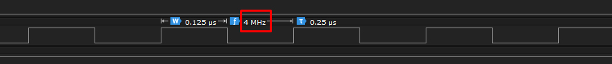
As you can observe, the speed of LL function almost 5.6 times more than HAL function!
Is it accidental? It is obvious no.
Some items have contributed in increasing the speed, in the following we will survey them.
Generally, if we want to give a reason, the reason is the implementation method of HAL and LL function. But this reason has some details that we should survey it precisely.
If you pay attention to the code that is written by LL function, you will see to set the microcontroller output pin to 0 and 1 the LL_GPIO_SetOutputPin and LL_GPIO_ResetOutputPin are utilized and in these functions two BRR and BSRR registers have used. But in the written code by HAL function this implementation just have done by a function that name is HAL_GPIO_WritePin and in this function just BSRR register is used.
What is the operation of these two registers? The BRR register is a 16bit register that is used to set the microcontroller pin to 0. The BSRR register is a 32bit register that first 16 bits of it is to set output to 1 and the second 16 bits of it is to set output to 0.
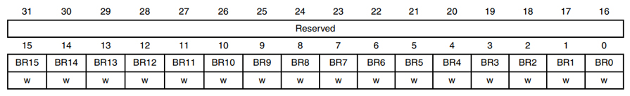
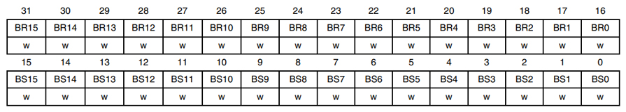
Actually ST company to set the microcontroller pins to 1 uses the first 16 bits of the BSRR register and to set the microcontroller pins to 0 uses the BRR register, but if you do not want to use the BRR register for any reason it is possible to use BSRR register for setting the microcontroller pins to 0 or 1.
We conclude with the above descriptions and images that despite the BSRR register we will not need to use BRR register. Yes, this is true conclusion, but we lose the speed. The main reason for lower speed of HAL function is this issue.
First pay attention to the implementation of the HAL_GPIO_WritePin:
|
1 2 3 4 5 6 7 8 9 10 11 12 13 14 15 |
void HAL_GPIO_WritePin(GPIO_TypeDef *GPIOx, uint16_t GPIO_Pin, GPIO_PinState PinState) { /* Check the parameters */ assert_param(IS_GPIO_PIN(GPIO_Pin)); assert_param(IS_GPIO_PIN_ACTION(PinState)); if (PinState != GPIO_PIN_RESET) { GPIOx->BSRR = GPIO_Pin; } else { GPIOx->BSRR = (uint32_t)GPIO_Pin << 16U; } } |
If the value of PinState is not equal to the GPIO_PIN_RESET so the aim is to set the microcontroller pin to 1 and the value of the second entrance that is mean GPIO_Pin should be in the first 16 bits of the BSRR register, otherwise the aim is to set pin to 0 and the value of the second entrance should be in the 16 bits of the BSRR register.
Well, first of all, in this function some conditional commands are used and we know surveying each of these conditions need to spend time, on the other hand in this function bit shift command(GPIO_Pin<<16U) used and need more time.
Up to here, using the conditional and shift commands are the factors in reducing the speed of the HAL functions.
Another factor of this speed difference is that the LL functions are not implemented as regular functions rather, these functions are implemented INLINE.
In the C language functions are used in two ways in the program, one method is that when the program reaches to the desired function, the program calls it. Another method is that before compiling, the body or code which is written in the function copies in a place of the program which use the function and no function is called during the execution of the program. These types of functions are known as INLINE functions.
Speed of INLINE functions is more than regular functions and if you are careful, in the definition of LL function the expression STATIC_INLINE__ is used which demonstrates these functions are INLINE.
So, there factors play main roll in this huge speed difference, consist conditional commands, bit shift and the functions that were implemented as INLINE. Of course, there are other influencing factors like object-oriented structures in the HAL functions are more than LL functions and we do not survey them due to less importance.
In the sixth part we will talk regarding the GPIO in the INPUT mode