In the second part of STM32 tutorials with LL function we talked about the number of processor bits and its advantages and disadvantages as well as got familiar with the principle of configuration. In this part of the tutorial, we want to teach you the Keil and STM32CubeMX in LL function. Then we will create a project by this software and finally we write a simple code through Keil. We will program the board by a programmer practically.
STM32CubeMX Software
This software is considered by ST company for the initial configuration. This software has a user-friendly graphical environment, and a user can config a microcontroller through just some click. In the following we will get more acquainted with the features of this software.
STM32F1 Software Framework
After the installation of STM32CubeMX, at first you must download the framework of the microcontroller series that you want to work on it. Here we use STM32F103C8T6, so we download the STM32F1 series. Pay attention that for each family of ST microcontrollers there is an exclusive framework which is usable for all the series of microcontrollers on that family.
To download framework like the image below from Help menu choose the Manage embedded software packages:
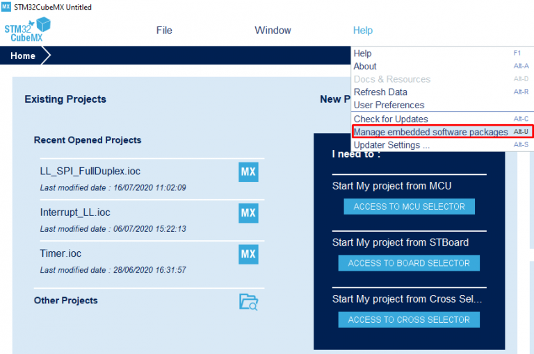
After this choosing the manage embedded software packages you will face a new tab:
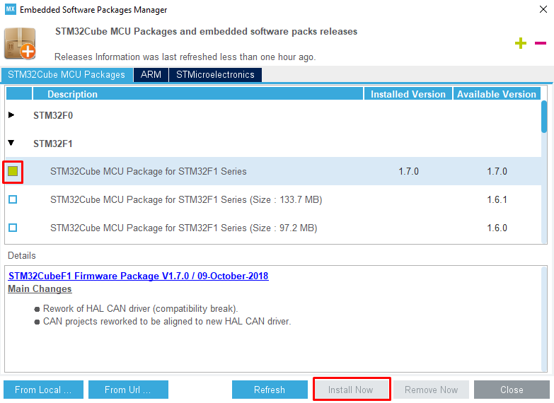
In this tab open the STM32F1 series and download the last version of package. To download you need to tick the small square left and then click on Install Now tab. If you pay attention to the picture above there are two other ways to import framework. one of the is local way and another is URL. It is time to create a project after finishing the download. To make a project like the image below select the New Project from File menu:
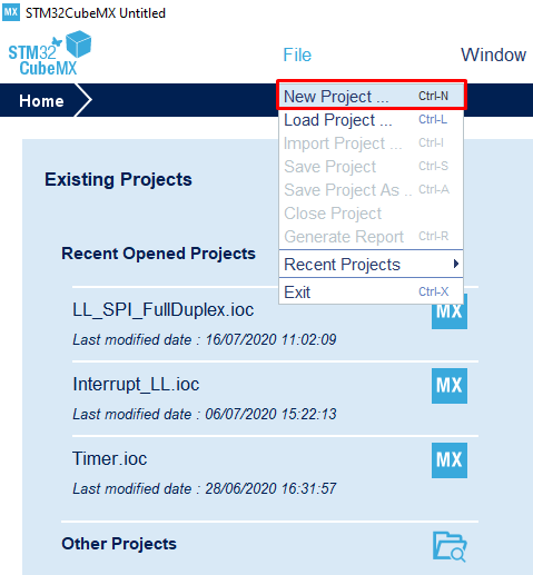
After selecting the New Project option, you will see the following window:
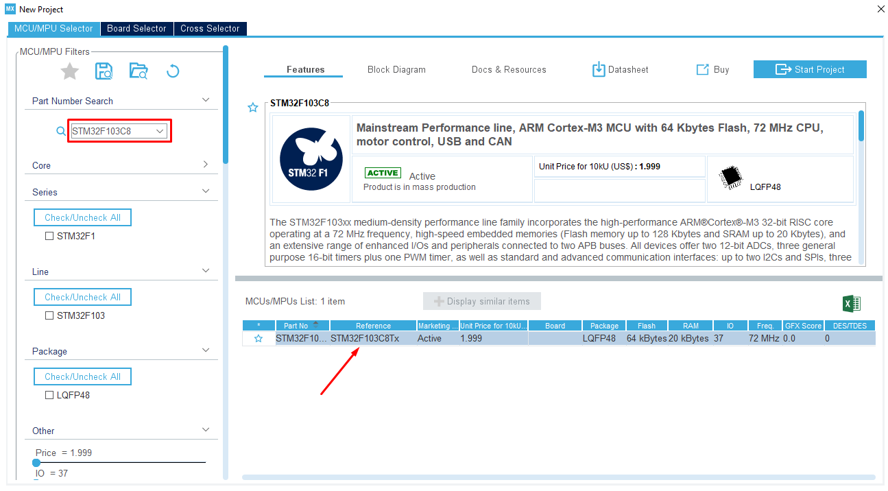
In this window in the specified location search the name of the microcontroller and then double click on it to go to the microcontroller configuration page. At first you should set the RCC (Reset and clock control) option:
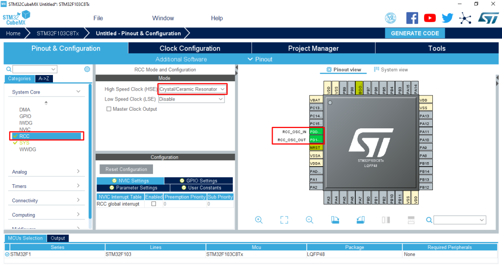
We want to use the board’s crystal so we set the RCC on Crystal/Ceramic Resonator.by enabling the RCC option, you will see the microcontrollers pins status are changed. When you set each peripheral or unit In the STM32CubeMX software, the status of the corresponding pins will also change graphically. In the next part we describe the setting of the RCC and clock comprehensively. In this part just set the parameters according to the images.
After this we should define how the microcontroller is supposed to program. DT microcontroller usually are programed through JTAG and SWD. Strongly recommended to search more information regarding JTAG and SWD on the internet. In this article we will utilize two methods. In the SWD method ST-Link programmer and in JTAG method J-Link method are needed. Also, it is possible to use J-Link in SWD mode for programming.
In fact, the main difference between the two methods is the number of wires that we use in programing. SWD protocol is needed less wire for programing a microcontroller. As you can see we will use two methods for programming the microcontroller.
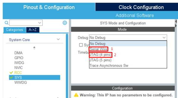
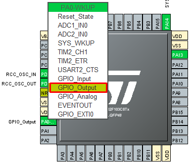
First, please select the method 1 to program the microcontroller through the ST-Link. Of course, by choosing each method it is necessary to set the corresponding setting in the Keil software. To write a simple code we put the one of microcontroller pins in output mode. To do this according to the image set PA0 pin to GPIO_Output.
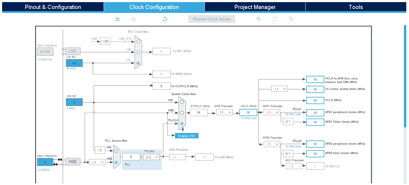
All the settings that we have done were in the Pinout&Configuration window. Temporarily, without knowing the reason please do the following settings in Clock Configuration window:
We have done all the demands for a simple project, now it is the time to transfer the configuration and settings to the Keil code editor environment. In the STM32CubeMX we can execute output for the code compilers. Three known and strong compiler which is possible to get output for them are IAR, Keil and STM32CubeIDE. Of course, here we tent to get output for Keil version 5 and edit and compile code in this editor and then program it on the microcontroller.
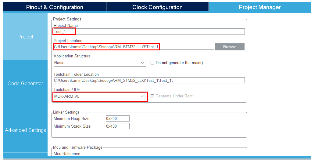
To do this set the configuration in Project Manager tab according to the following description. In project tab according to the below image choose a name and location for your project and in the Toolchain/IDE part select MDK-ARM V5 which is corresponding to the Keil version 5:
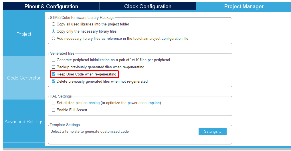
In the Code Generator part set the configuration according to the image, caution that select the Keep User Code When re-generating item, otherwise each time if you reconfigure the settings your written codes will be clean in the Keil software.
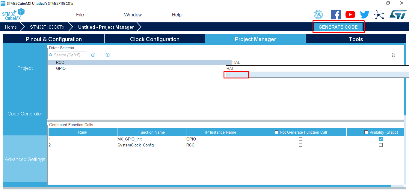
And finally in the section Advanced Setting according to the below image select the LL functions (the default value is on HAL functions) and click on the GENERATE CODE option.
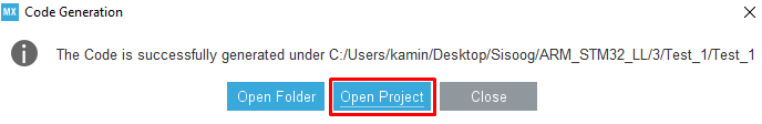
After producing the output for the Keil software we face the below message that we should click on the Open Project to open the project.
Keil Software
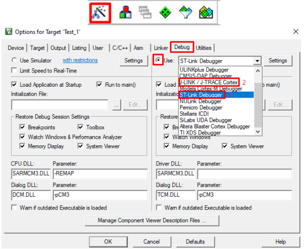
Keil is one of the strongest editors for edit and compile the code. The ancillary features of this software namely debugging environment, time analysis of the microcontroller, connecting with the different of programmers and choosing compiler causes you do not need to any other software. After opening the Keil at first we should configure the programmer.
As we mentioned above we can program the ST microcontroller in two ways (in this article we just describe two methods otherwise there are other methods like Boot and UART to programming the microcontroller). In the below picture if we select option number 1 we should use ST-Link programmer through SWD protocol as well as if we select option number 2 we should use J-Link programmer and JTAG protocol.
Our goal was to introduce the STM32CubeMX and Keil software in this article but to the configuration of the applied settings we will write a simple code and program it on the board. As you know or maybe do not know the simplest code in electronic world is LED blinker which is correspond to Hello World in computer world.
For LED blinker we should write the below code in while loopà
|
1 2 3 4 |
LL_GPIO_SetOutputPin(GPIOA, LL_GPIO_PIN_0); LL_mDelay(500); LL_GPIO_ResetOutputPin(GPIOA, LL_GPIO_PIN_0); LL_mDelay(500); |
We will analyze this code in GPIO article. Also keep in mind to have a tidy code and want to modify the code in STM32CubeMX and get output again as well as to prevent deleting the codes that are written by you, you should write your code in each section similar to the below pattern between two phrases.
|
1 2 3 4 |
C /* USER CODE BEGIN */ /* USER CODE END */ |
Well, it is time to compile the code and then download it into microcontroller to see the result. To do this you should follow the operation according to the below image and click on the options respectively:

In the fourth part of the RCC unit, we will survey the configuration of the Clock, PLL and Reset comprehensively and introduce a simple tutorial board for testing the codes.