In the third part of LL functions tutorial, we learned how to generate a simple project and microcontroller configuration. At the end we got the output code for Keil software and after compiling programed it on the microcontroller. If you remember when we approached to the RCC part and the settings of the Clock, skipped it and just did some configuration without knowing the reason.
In this part of tutorial our aim is to discuss about the Clock and Reset which is in RCC (Reset and Clock Control) option comprehensively. In addition, we learn other concepts such as PLL, Oscillator, Crystal and finally introduce a tutorial board to use.
Let us start the discussion of this article with what a Clock is and why should it exist.
Clock
If we consider the structure and performance of a computer or microcontroller similar to structure and performance of a human body, CPU is similar to brain, Clock source is similar to human heart and the clock signal itself is the blood which circulate through the vessels by heart so that the brain can sent its commands to other body organs.
Actually, the brain by using the veins and the blood that flows in these veins can command to body organs and control them and if there is an interruption in blood flows to the brain, the whole system of the human body is disturbed.
In the microcontroller the Clock play the main role and if the clock is interrupted for a moment or has a problem, whole microcontroller is interrupted.
In the digital electronic there are circuits namely synchronous circuits, and these circuits need Clock pulse to match together and without Clock it is not possible to work.
So far we have understood the function of the Clock pulse and why it should exist. Now we need to get acquainted with the nature of the Clock and how to make it.
The below figure demonstrates the ideal Clock pulse:
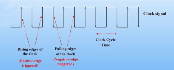
To produce the signal similar to above image we need separate circuit which called the Clock source.
An important point to pay attention to is the difference between the nature of Clock source and power supply. In the following, we discuss fundamentally the difference between Clock source and power supply.
To convey the concepts faster and better, the relationship between the heart and Clock source was expressed in general and we considered both of them to be equivalent, however this relationship is not accurate and correct. For more detailed connections between them, follow the below clarification.
On the place that we mentioned the heart is similar to the Clock source should be modified. The heart is precisely similar to power supply not to Clock source. Actually, the Clock source gain its power from the power supply and produce the Clock pulse as output.
After above modifications, we should say the heart is the power supply as well as when and how the heart flows the blood to brain and other organs can be likened to the Clock source and the Clock pulse.
Our body system can be alive but have problems in performance at the same time, this situation can happen for a microcontroller without Clock pulse source which means that the microcontroller is on but cannot working properly.
We try to simile the microcontroller to the human body system and describe the concepts fundamentally. we learned regarding the difference between Clock source and power supply.
Clock source circuit
Now is time to survey the Clock pulse circuit, below the image demonstrates the simplest circuit for Clock pulse production.
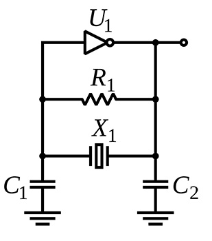
In the microcontrollers to produce the Clock pulse the above circuit can be use in two ways. One way is to use it as an external part near the microcontroller another way is using part of the circuit near the microcontroller because the other part is inside the microcontroller.
In the second way just a crystal and two capacitors are placed outside the microcontroller and the other part of the circuit is placed inside the microcontroller. The external part is named feedback circuit.
When we use all the circuit in outside and near the microcontroller this circuit is called oscillator and when we use some part near the microcontroller this circuit is called crystal.
In addition to above circuits in supplying the clock source there is another internal RC oscillator circuit inside the microcontroller which we can use it as a clock source without any external crystal or oscillator circuit, but usually due to inaccuracy and temperature dependence rarely internal RC is uses.
Reset
Have you ever thought that when we say a microcontroller is reset what happens exactly?
The general concept of reset is the things that we know from the past, it means a return to an initial state. Now if we want to answer this question precisely as an electronic engineer, we should say that when the reset action happens the PC (Program counter) backs to the first line of the program. In the microcontroller there is a register that name is PC (Program counter), the number in this register defines which line of code should be executed. When a microcontroller is reset the value of PC register is changed and the first line of the code starts to execute.
Microcontroller can be reset through the hardware and software way; at this time, we postpone the software method and just talk about the hardware methods. The hardware methods include turn on time, turn off time and the time that the reset pin of microcontroller reach to the voltage level that reset status is considered for it.
It is necessary to protect the microcontroller from the unwanted reset and more safety, connect to the below reset circuit:
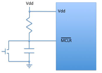
The target of this tutorial is not about the hardware designing for the microcontroller and in some vital cases like Clock and Reset circuit, we limit ourselves to a series of general descriptions of circuits.
Now we want to import the settings of Clock and Reset into the software.
RCC (Reset and Clock Control)
At first look at the below image:
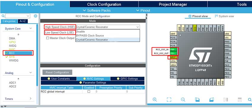
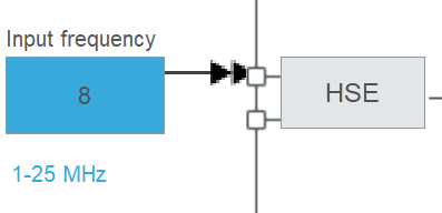
As you can see in the above image, from the external clock source just HSE is enable which is graphically defined. One of the advantages of STM32CubeMX is that each set of configurations result is demonstrated graphically. As an example, if we select crystal instead of the oscillator, HSE part like the image below changes. Actually, for the crystal two pins and for the oscillator one pin is needed.
As a note if you see the HSE setting when the crystal is selected and compare it when the oscillator been chosen, you will understand the entrance frequency limitation is different. By choosing the crystal, the crystal frequency can be between 4 and 16 MHZ, while this frequency for the oscillator is between 1 and 25 MHZ.
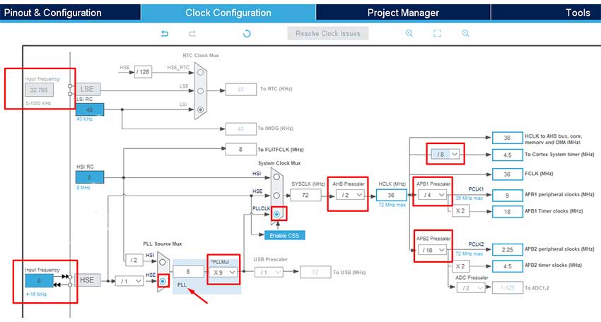
Through multiplexer we can choose from which source the system clock is provided. By the PLL we can increase the frequency as well as by prescaler we can decrease the frequency.
Consider the PLL like a block which receives the frequency as an entrance and multiplies the frequency to a number and delivers it in output. For the Prescaler this block receives the frequency and then divides it to a number and deliver it to the output.
Also, we can see both internal RC oscillator in the LSI and HSI part. We usually do not use these oscillators as a clock source.
This article regarding the Clock and Reset ends here and at the end we introduce to you a tutorial board.
From the fifth part we want to implement the codes practically on the board. To do this we will use very simple board namely ‘blue pill board’ that you can see in the image below.
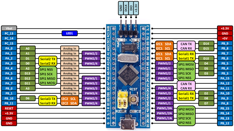
In the above image each pin of microcontroller is defined adequately. In each article we will lunch the microcontroller peripherals.
In the fifth part we will talk about the GPIO-Output and survey the LL and HAL functions comprehensively. On the fifth part some vital notes are cited, and you can understand the secret of the high speed of LL functions.